Medium Voltage (MV) Asynchronous motors are used in several industries in different applications. This article aims to explain principles of energy saving with MV frequency converter applications as such motors.
Terminology first: Frequency Converter means and inverter at core. Drive is general name for the power electronic devices used for motors. In our case they all address the same equipment. We will use the Frequency Converter for the rest of the article.
Frequency converters are used when the application requires to change the speed (RPM) of the motor.
As principle squirrel cage asynchronous motors require less maintenance compared to slip ring asynchronous motors. However, when started direct on line (DOL) the inrush current is 6 to 8 times of the nominal current (In). This excess amount of current results on electrical and mechanical stress on the motor and on the energy grid. The supply network (grid) should have enough spare capacity to supply the power needed during the DOL starting period. On the motor side the inrush current results in heating of the motor. Thermal capacity is being used fast. Back to back start should be done carefully in order to avoid damage on the motor windings and insulation. Mechanically speaking sudden start means the motor shaft and the load takes a shock. In time this may result in failures. In some cases it is necessary to use bigger size motor to avoid mechanical failures on the shaft. In mechanical stress, moving parts result in a shorter mechanical life with the force generated. The best method to prevent these negative factors is not to exceed the motor rated current. We can achieve this by giving way through frequency converters. (If the application does NOT require variable speed MV Soft Starters are also a valid option to minimize and/or avoid the electrical/mechanical shocks. Please consult with us for further details).
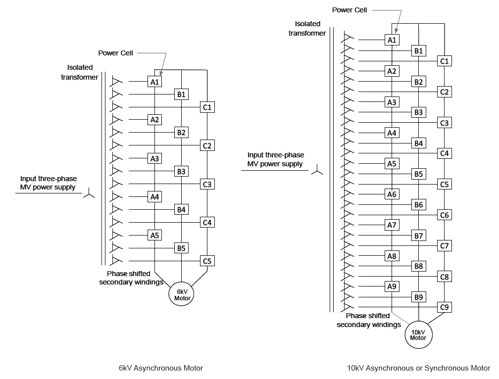
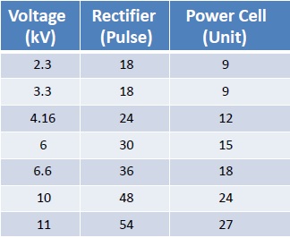
In this article we are going to take a close look to the Medium Voltage Frequency Converters which has multi-cell structure. Below diagram shows the principle of how it works. The voltage output is achieved by connecting the power cells in series. For 6kV output there are 5 cells for each phase. For 11kV output 9 low-voltage power cells are needed for each phase.

The basic structure of the low voltage power cell is as follows:

The frequency converters which have multi-cell architecture match the IEE standards for harmonics. Basically the current and voltage forms are very close to sinusoidal wave form. 6kV multi-cell FC is 36 pulses, which reduces harmonics a lot compared to frequency converters which are 12 or 24 pulse output.
This also has a positive effect on the power applied to the motor. For retrofit applications for old motors, 36 pulse FC units should be preferred.

By-Pass structure (Optional):
Medium voltage frequency converters are microprocessor controlled electronic products. They have advanced protection parameters for both the motor and the drive, preventing possible damage during operation. Preventing possible breakdowns before they get bigger also gives the on-site maintenance team the advantage of performing maintenance more planned and with smaller costs.
It is also possible to apply by-pass for the MV frequency converters. This may be useful if the motor is required to run at nominal speed for an extensive time (hence saving the losses on the FC) or to do maintenance work on the MV FC.
Our Hiconics brand MV frequency converters have both air- and water-cooled solutions. Water cooling is preferred if the environment where the FC is erected is harsh and dirt and it is not possible to get fresh air for cooling. Many sectors such as iron and steel, water sector, power plants, wood sector prefer air-cooled MV VFD, while water-cooled MV VFD can be preferred in exploded (exproof) environments such as the mining sector.
In addition, regenerative products may be needed in the case when the engine is operating in four zones. Regenerative frequency converters can also be produced in Hiconics MV VFD products. In these products, while drawing energy from the network according to the working area of the motor, it can also feed energy back to the network. Medium voltage frequency converters also have different models that can give way to asynchronous and synchronous motor types, as well as at the low voltage level.
MV frequency converters make your work easier in the business with advanced protection parameters. MV electric motors are very large and heavy in terms of their structure. At the slightest deficiency, large maintenance costs can arise on them. Electric motors; are exposed to the influence of overcurrent, over-temperature and overvoltage, resulting in undesirable effects. In order to extend the life of the motor, it is necessary to monitor these three values. TH MV FC with motor protection functions will meet these demands.
Flexible communication options :
All parameters in the MV Frequency converter can be transferred to a controller or SCADA environment with a communication infrastructure (RS485 Modbus RTU, Profibus, Ethernet).
Working at different voltage levels (according to field conditions):
Medium voltage frequency converters have a special multi-output MV transformer. For each power cell, the transformer has individual secondary output leads. For example, if there is a voltage level of 10 kV in the enterprise and the motor to be started with the MV drive is in the order of 6.3 kV, this conversion is provided by selecting the transformer in the MV VFD during manufacturing. In other words, there is no need for a separate power transformer between the energy receiving point and the MV frequency converter. This means saving additional costs within the enterprise. The business also provides financial advantages. Hiconics Medium voltage frequency converters are manufactured according to IEEE 519 standards. The MV transformer dry type used in the product is 8% impedance, copper coiled.
Cell By-Pass structure (Optional) :
There may be applications where production should not be interrupted. Therefore, if the optional “cell by-pass” is included in the frequency converters, the driver detects the faulty power cell and bypasses it. Thus, the motor continues to operate, even at a speed lower than its rated speed. It resets the star point to avoid uneven charges and creates a new star point to produce the balanced output for each phase. When the defective power cell is replaced, the medium voltage frequency converter increases its speed to the previous set value and returns to the initial speed value. Thus, production is not disrupted. Power cells can be easily replaced with a new one. The cell by-pass feature is limited to 1 for each phase and this feature works up to 3 (3 phases) in total. If more than one power cell is damaged in the same phase, this is a serious cause of failure and the MV frequency converter comes to a standstill.
Following are few items to be considered for choosing the right solutions;
- Type (asynchronous or synchronous) and age (older the motor better to select MV FC with sinusoidal output),
- The power grid capacity and voltage level, as well as motor voltage level should be considered. (The transformer in the MV VFD can be specially manufactured for the application, like Input: 10 kV Output: Like 6.3 kV)
- The application type and load requirements (Exp: Fan, Pump, Mixer),
- The operating temperature must be selected to give the drive lossless power.
- Load requirements according to application type
(For example, 120% load at 60 sec or 150% load at 60 sec) - Requirements for communication and integration to the existing control systems,
(e.g. Modbus RTU, Profibus DP, Ethernet,) - IP protection class of the cabinets,
- Integraton with the existing medium voltage switchgear needs to be determined.
For your MV frequency converter needs, you can contact us from our phone numbers or www.cedetas.com.tr website.
![]()


