LoRaWAN Network Structure
LoRaWAN is a long distance and low power consumption oriented wireless communication protocol. It has a distance of 2-3 km in the city, 5-7 km in campus and similar places, and 15 km in open areas. LoRaWAN is designed for various battery-powered sensors in the field to transmit data to the cloud environment over gateways. Data received from these sensors are temperature, humidity, air quality, water leakage status, water level status, an electrical contact status, electricity/water/natural gas counter value, door/window open/closed information, light intensity, presence sensor information, fire alarm information. , can be any value obtained from another electronic device.
LoRaWAN provides bidirectional communication, so that not only information can be received, but also command sent to end devices. Various commands can be given, such as opening and closing a contact, changing device settings, updating software, opening and closing the valve, starting and closing the pump.
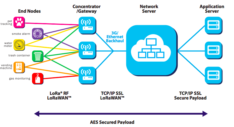
The general structure of the LoRaWAN network is as shown in Figure.

The devices at the edge communicate with the gateways connected to the internet with the help of LoRaWAN. The task of these gateways is to forward the packets from the end devices to the Network Server (LoRaWAN Network Server). Gateways do not save the data they transmit, they cannot see its content. Generally speaking, they just provide the conversion function. A device can send the same message to multiple gateways at the same time, when these messages are forwarded to the network server, duplicate copies of the same message are deleted. A single copy is processed.
There are 4 basic elements required to build a LoRaWAN network,
- End devices
- Gateways
- Network server
- Application server
The task of the end devices is to collect data from the end and transmit it up, as stated before, and to apply the commands from above.
Gateways, on the other hand, have the task of providing radio communication with end devices and communicating these devices with servers using an internet connection.
The network server collects incoming data through LoRaWAN gateways, deletes duplicates of repetitive messages, provides management of the network (RF parameters, devices, etc.).
The application server is the part where data is last collected and visualized, or commands can be executed. It is the unit closest to the user side.
Installation
Deploying a LoRaWAN network is configuring the edge devices, gateways, network server, and application server, and getting communication up and running.
In general, there are two commissioning methods. These are OTAA (Over-the-air Activation) and ABP (Activation by Personalization). In the OTAA method, cryptographic keys are not placed directly into the end devices, they are dynamically generated from the device address and other variables. This is how network traffic is encrypted. This method can be translated into our language as remote activation. The other method, ABP, is provided by embedding relevant cryptographic keys in devices. These switches can be found with the device set at the factory.
Commissioning is achieved with the following steps.
- Gateway configuration
- Configuration of application server and network servers
- End device activation
Gateway Configuration
By adjusting the various parameters of the gateway, healthy communication with the end devices and the network server should be ensured. The most important parameters of the gateway are RF communication frequency groups (channels) and time settings. LoRaWAN RF settings are divided into regional groups based on different legal requirements in different regions. Some of these regional setting groups are as follows. EU868 and EU433 adjustment groups can be used in our country.
- EU868
- US915
- CN779
- EU433
- AU915
- CN470
- AS923
- KR920
- IN865
Regional tuning groups got their numbers from the frequency value. This selection must be made on the gateway.
To minimize power consumption, a LoRaWAN edge device opens two receive windows after transmitting data instead of operating in receiver mode all the time. It receives signals from above (gateway) in one of these receive windows. It is important that this parameter, which is included in the regional parameters, is also correct, as the reception windows are opened after a certain period of time after sending.
Another important setting to be made on the gateway is to register the network server IP address and port. Thus, the gateway forwards the packets it receives to this server.
Network Server Configuration
The network server can be provided by the company that installed the system, it can run in the cloud or on the user’s local server. Region settings, general network settings should be made on the network server, and RF parameters should also be set.
End Device Activation
For edge devices to be enabled, device information must be added to the application server. The addition process differs according to the OTAA and ABP methods.
OTAA Method
For this method, the following information on the end device must be entered through the application server.
• DEVEUI: It is the unique address of the device. Its size is 8 bytes.
• APPEUI: The unique address of the application. Its size is 8 bytes.
ABP Method
For this method, the following device parameters must be registered via the application server.
- AppSKey: Application session key.
- NwkSKey: Network session key.
- DevAddr: Device address. It is automatically assigned in OTAA mode, here it must be entered manually.
After these stages, the end devices can communicate with the network server and the application server can connect to this network server and receive the desired data over various protocols.
![]()


