Medium voltage (MV) electric motors are used in almost most of the medium and large scale factory/industrial sites. They appear in various application areas, sometimes in fan / pump applications and sometimes in mill applications under heavy conditions. It is necessary to make sure that these engines are working in appropriate working conditions in order not to interrupt the production of the enterprises. The mechanical and electrical stresses that occur on the motor over time reduce the life of the motor. In order to reduce these effects, it is necessary to start with frequency converters (MV VFD) where speed adjustment is desired instead of primitive starting methods.
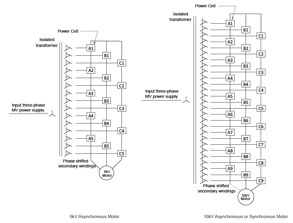
The desired medium voltage level is achieved by increasing the number of low voltage power cells. For example, it is done by connecting 5 low voltage power cells in series for each phase at the level of 6 kV. Similarly, for the 11 kV range, the 11 kV range is obtained by connecting 9 low voltage power cells in series to each phase.

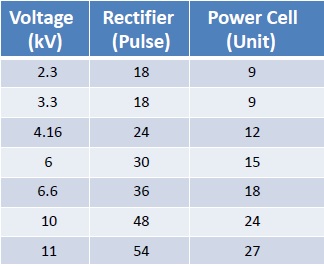
The total number of power cells used according to the kV range is shown below.

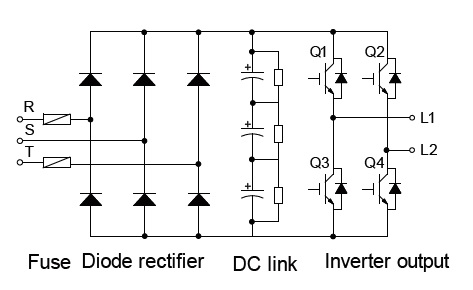
The basic structure of the low voltage power cell is as follows:

At medium voltage level, frequency converters have the effect of reducing harmonics. For example, using 36 pulse power cells at 6.3 kV level will reduce the effect of harmonics in the network. In order to get a more affordable price in the market, some competitor companies may offer 24 pulse or 30 pulse products for the 6.3 kV range. At this point, the consumer should act consciously. It should prefer products with high pulse output.
By-Pass structure (Optional):
Medium voltage frequency converters are microprocessor controlled electronic products. This advantage has brought advanced protection parameters for both the motor and the driver and prevents possible damage to the motor in operation. Preventing possible breakdowns before they get bigger also gives the maintenance team the advantage of carrying out more planned and less costly maintenance. If it is desired to disable MV frequency converters for maintenance purposes, manual bypass or automatic bypass cabinets are needed. Thus, in mandatory applications, the relevant motor can be started directly over the mains (Direct On Line).
There are medium voltage frequency converters (MV VFD), according to the sector, there are also water cooled frequency converter models apart from air cooling. Our Hiconics brand MV frequency converters have both air and water cooled solutions. For example, many sectors such as iron and steel, water sector, power plants, wood sector prefer air-cooled MV VFD, while water-cooled MV VFD can be preferred in ex-proof environments such as the mining sector. In addition, regenerative products may be needed when the engine is operating in four zones. Regenerative frequency converters can also be produced in Hiconics OG VFD products. In these products, while drawing energy from the network according to the operating region of the engine, it can also supply energy to the network. Medium voltage frequency converters have different models that can start asynchronous and synchronous motor types as well as at low voltage level.
MV frequency converters make your work easier with advanced protection parameters. OG electric motors are very large and heavy in nature. In the slightest deficiency, large maintenance costs may arise in the engines. electric motors; They are exposed to the effects of over-current, over-temperature and over-voltage, and are subject to undesirable effects. These three values should be monitored in order to extend the life of the engine.
Flexible communication options:
In all three cases, both the driver and the motor must be protected. Many similar protection functions can be monitored using frequency converters. All parameters in the MV frequency converter can be transferred to a controller or SCADA environment with a communication infrastructure (RS485 Modbus RTU, Profibus, Ethernet..etc).
Working at different voltage levels (according to field conditions):
Medium voltage frequency converters have their own multi-output MV transformer. For each power cell, there are separate secondary output terminals on the transformer. For example, if there is a voltage level of 10 kV in the enterprise and the motor to be started with the MV driver is at the level of 6.3 kV, this transformation is provided by the appropriate selection of the transformer in the MV VFD during manufacturing. In other words, there is no need for a power transformer between the energized point and the MV frequency converter. This means savings in additional costs within the business. The business also gains financial advantage. Hiconics medium voltage frequency converters are manufactured according to IEEE 519 standards. The MV transformer used in the product is dry type, 8% impedance, copper winding.
Cell By-Pass structure (Optional):
If there is a problem in one of the power cells while medium voltage frequency converters are active, there may be places where production should not be interrupted. Therefore, if the optional “cell bypass” is included in frequency converters, the driver detects the faulty power cell and bypasses it. Thus, the motor continues to run even at a lower speed than its nominal speed. It re-adjusts the star point to prevent unbalanced loads and creates a new star point to produce the same power in each phase. When the defective power cell is replaced, the medium voltage frequency converter again increases its speed to whatever the previous set value is and goes back to the first speed value. Thus, production is not interrupted. Power cells are in a structure that can be easily replaced with new ones. Cell by-pass feature is limited to 1 for each phase and this feature works up to 3 (3 phases) in total. If more than one power cell is damaged in the same phase, this is a serious fault and the MV frequency converter stops.
If we want to list the issues to be considered in articles;
- The product should be chosen according to the engine structure.
(For example: According to asynchronous or synchronous motors) - What is the MV VFD input voltage and the application voltage to be applied to the Motor?
(The transformer inside the MV VFD can be specially wound. Input: 10 kV Output: 6.3 kV etc.) - It should be selected according to the application type.
(Exp: Fan, Pump, Mixer…etc.) - The operating temperature of the drive must be selected to provide power without loss.
- Install rate by application type
(For example, 120% loading in 60 sec or 150% loading in 60 sec) - Is a special communication structure desired?
(For example Modbus RTU, Profibus DP, Ethernet,) - IP protection class
(In some special applications, high IP protection may be required.)
For your MV frequency converter needs, you can reach us from our phone numbers or our website at www.cedetas.com.tr.
![]()


